


 Electrical Guides
How to Wire a Smart Streetlight: Step-by-Step
 David Reynolds
 Oct 11, 2026
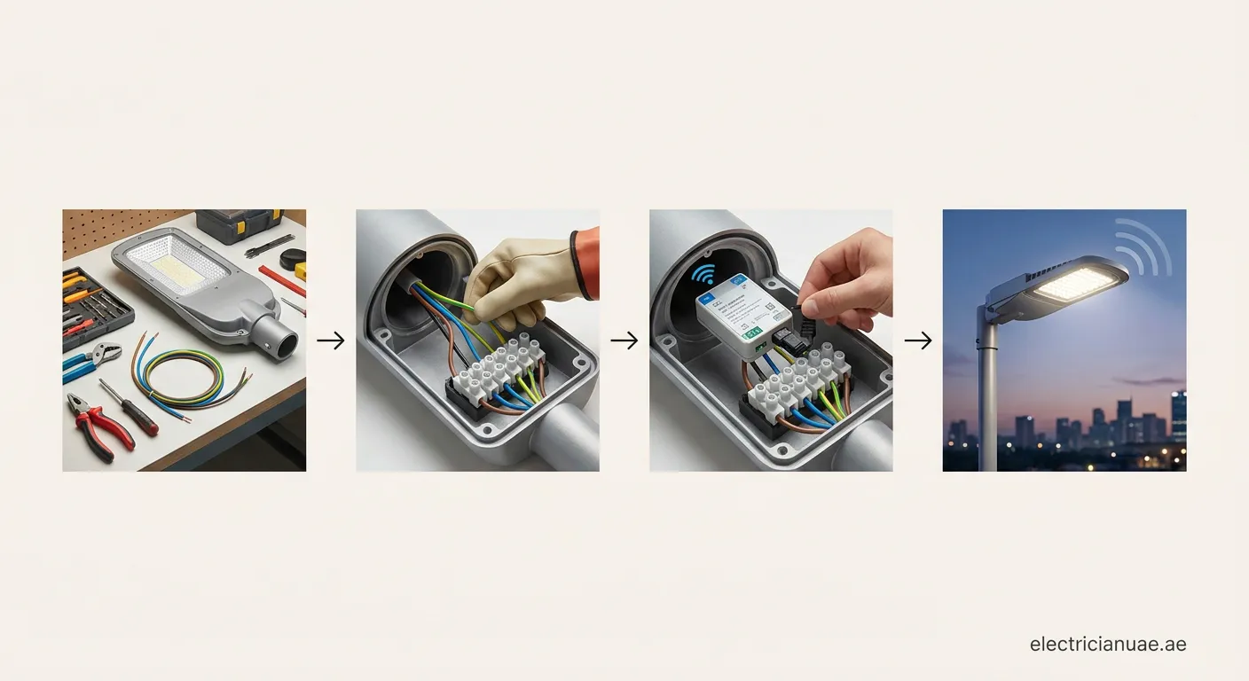
Modern municipal and residential lighting requires efficiency and remote connectivity. Discover how to wire a smart streetlight safely, from pole cable runs to intelligent IoT controller setups.
Understanding Smart Street Lighting Architecture
Upgrading infrastructure with intelligent outdoor luminaires delivers optimized power consumption and centralized control. Learning how to wire a smart streetlight demands a solid understanding of both high-voltage AC mains and low-voltage control circuits. Unlike legacy fixtures with mechanical photocells, modern units integrate microcontrollers, ambient light sensors, and wireless IoT nodes (such as LoRaWAN, Zigbee, or cellular NB-IoT).
Essential Tools and Safety Precautions
Prior to beginning any installation, safety must be your top priority. Always de-energize the supply circuit at the main distribution board and lock it out.
- Insulated electrician hand tools (rated up to 1,000V)
- Digital multimeter and clamp meter for voltage verification
- IP67/IP68 rated waterproof junction boxes and gel-filled connectors
- Heavy-duty wire strippers, torque screwdrivers, and crimping tools
- Standard PPE including dielectric gloves, safety harness, and eye protection
Crucial note: Never attempt electrical terminations in wet conditions or while the main feeder line is energized.
Step-by-Step: How to Wire a Smart Streetlight
Follow this systematic procedure to complete your smart streetlight wiring correctly and safely.
1. Preparing Conduit and Feeder Cables
Pull three-core outdoor armored cable (Phase, Neutral, Protective Earth) through the pole shaft up to the luminaire mounting bracket. Leave at least 300 mm of slack at both the base access hatch and the top terminal compartment for easy maintenance.
2. Mains Power Connections
Strip the outer insulation carefully without nicking internal conductors. Connect the incoming lines to the surge protection device (SPD) and LED driver terminals:
- Brown or Black (Phase/Live): Connect to terminal marked L or ACL.
- Blue or White (Neutral): Connect securely to terminal N or ACN.
- Green/Yellow (Protective Earth): Fasten directly to the luminaire metallic chassis grounding stud.
3. Integrating the ANSI C136.41 or Zhaga Smart Receptacle
Smart luminaires utilize standardized NEMA 7-pin or Zhaga Book 18 sockets on top of the housing to communicate with intelligent nodes.
- Connect the continuous AC power leads to pins 1, 2, and 3 for the sensor power supply.
- Attach the 0-10V or DALI-2 dimming control wires to low-voltage pins (typically Violet for Dim+ and Gray/Pink for Dim-).
- Verify polarity carefully; inverted signal polarity will prevent remote automated dimming commands from functioning.
4. Grounding and Surge Protection Verification
Outdoor luminaires are exposed to severe atmospheric voltage spikes. Ensure the SPD ground lead is bonded with low impedance to the earth rod at the base of the mast.
Final Testing and Commissioning
After completing the smart streetlight installation and wiring, seal all access compartments using weatherproof gaskets. Restore AC mains power, measure line voltage, and verify that the intelligent communication controller pairs successfully with your central management system.
Professional Smart Lighting Support
Mastering smart street lighting ensures long-term safety and energy savings. If you face electrical faults or need expert maintenance, our specialists provide Short-circuit-repair Al Butina and comprehensive field services across the area.
 smart lighting, electrical wiring, outdoor lighting, iot streetlights
